

the TEST trg./src.at (fig.1) got my interest by it's switching capacitor name values (1µF) v. V.OUT parameters -- I.max = 50mA U.TOT = 30V . . .
. . . the simulation showed that the transistors at the same "shoulder" are OPEN @ the same (short) time + the generator wave forms were somewhat not that you'd expect
(i guess presented in the ® order ) the figures show the improvement/TEST steps - to meet proposed OUTPUT parameters to this 9V : 30V converter
note : the peak currents approach 1A range - the averages - are the way over the specs of the 1-s of the initally shown* transistors (in test the 2N3906*,-04* was used to get the oscillations started) /!\ -- you likely can't build any of the shown grids ( using these* transistors ) that would survive the switch ON + further more (i suppose) using the 6LF22 / 6LR61 or alternate won't meet the power demand of "this" converter the 6x AA / LR6 or better is more realistic
Figures ::
[EOF]
. . . the simulation showed that the transistors at the same "shoulder" are OPEN @ the same (short) time + the generator wave forms were somewhat not that you'd expect
(i guess presented in the ® order ) the figures show the improvement/TEST steps - to meet proposed OUTPUT parameters to this 9V : 30V converter
note : the peak currents approach 1A range - the averages - are the way over the specs of the 1-s of the initally shown* transistors (in test the 2N3906*,-04* was used to get the oscillations started) /!\ -- you likely can't build any of the shown grids ( using these* transistors ) that would survive the switch ON + further more (i suppose) using the 6LF22 / 6LR61 or alternate won't meet the power demand of "this" converter the 6x AA / LR6 or better is more realistic
Figures ::
- Fig.1 :: the ® - a lot of question marks
- Fig.2 :: 68% OUTAVG 28V 51mA INAVG 8.4V 250mA
- Fig.3 :: 64% OUTAVG 25V 44mA INAVG 8.5V 200mA
- Fig.4 :: 74% OUTAVG 29V 51mA INAVG 8.4V 230mA
- Fig.5 :: 79% OUTAVG 35V 63mA INAVG 8.3V 340mA
- Fig.6 :: 74% OUTAVG 38V 43mA INAVG 8.4V 260mA
 Fig.1 |  Fig.2 |  Fig.3 |
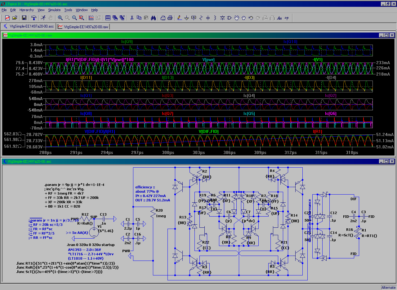 Fig.4 |  Fig.5 |  Fig.6 |
[EOF]
No comments:
Post a Comment